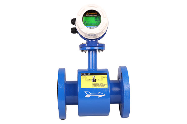
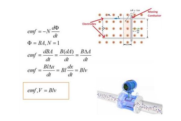
Electromagnetic flow meters work on Faraday’s law of electromagnetic induction, which states that a conductor moving through a magnetic field induces a voltage proportional to its velocity.
The flow meter contains two electromagnetic coils placed on opposite sides of a non-magnetic measuring tube. Inside, electrodes detect the voltage generated as the conducting fluid passes through the magnetic field. The inner surface of the tube is lined with an insulating material to prevent interference and withstand fluid properties.
When current flows through the coils, a magnetic field is created across the tube. As fluid moves through this field, it acts as a conductor and generates a voltage. This voltage is detected by the electrodes and sent to a transmitter, which calculates and displays the volumetric flow rate.
This design ensures no obstruction to flow and provides high accuracy for various conductive liquids.


Measurement formulas
The induced voltage in the fluid is determined using:
U=B×d×vU = B \times d \times v
Where:
-
UU = Induced voltage
-
BB = Magnetic flux density
-
dd = Distance between electrodes
-
vv = Average flow velocity
Since BB and dd are constant, UU is directly proportional to vv.
The volumetric flow rate is calculated as:
Q=A×vQ = A \times v
Where:
-
QQ = Volumetric flow rate
-
AA = Cross-sectional area of the tube
-
vv = Flow velocity

