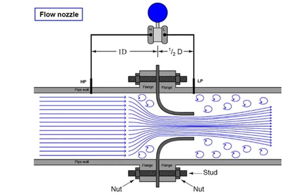
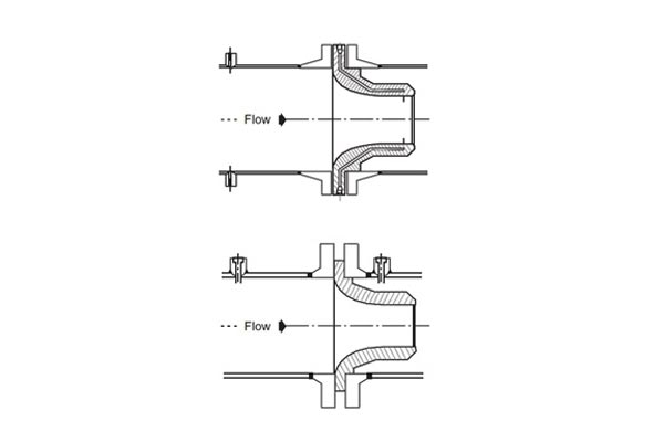
Flow nozzles are differential pressure devices designed with a smooth convergent section leading to a cylindrical throat. The throat, being the smallest diameter, causes fluid velocity to increase and static pressure to drop as per Bernoulli’s principle.
Pressure taps are positioned upstream and downstream of the nozzle to measure this differential pressure. These taps may be single holes or an annular ring of equally spaced holes.
As fluid enters the nozzle, the velocity rises and pressure drops at the vena contracta. Exiting the nozzle, the flow expands, velocity decreases, and pressure recovers. This pressure difference is captured by differential pressure transmitters to calculate flow rate using:
Q2=K×ΔPQ^2 = K × ΔP
Where:
-
QQ = Flow rate
-
KK = Constant for the nozzle type
-
ΔPΔP = Pressure differential
Flow nozzles are valued for their durability, minimal maintenance, and suitability for high-temperature, high-pressure applications.


Types of flow nozzles
-
ISA 1932 (Weld-in type)
Developed by ISO, this nozzle is ideal for permanent installations in pipelines under 2 inches. Corner taps are placed in the flanges upstream and downstream of the nozzle, making it suitable for high-pressure, high-temperature processes. -
ASME Long Radius – Low Beta Ratio (Flanged type)
This nozzle, with a beta ratio of 0.20–0.5, is widely used in power plants. Throat taps are located in the cylindrical section for accurate measurement. It fits between pipe flanges and is easy to install or remove. -
ASME Long Radius – High Beta Ratio (Holding ring type)
With a beta ratio of 0.25–0.8, this nozzle is installed using a holding ring and locating pins to avoid welding dissimilar materials. Recommended for pipes 4 inches and above, it is ideal for large diameter pipelines and heavy-duty applications.
Materials commonly used for these nozzles include stainless steel, bronze, Monel, and chromium alloys.

