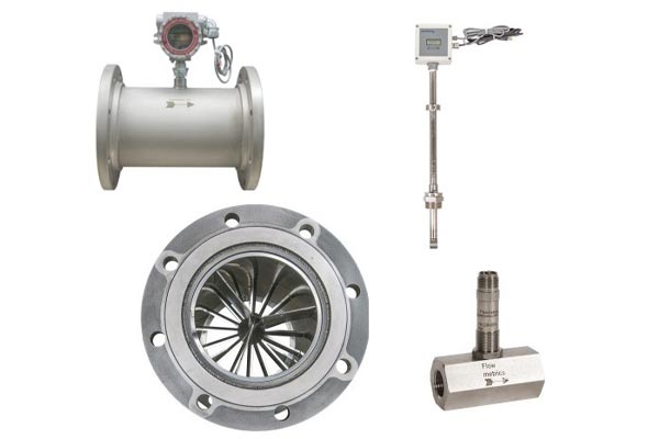
The Turbine flow meter is a highly accurate and reliable device for measuring fluid flow across a wide range of industries. It consists of a housing (flow tube), a multi-bladed rotor mounted on a shaft, support brackets, a pickup sensor, and a transmitter. The rotor spins freely on the shaft when fluid flows, while supports act as flow straighteners to minimize turbulence. The pickup sensor, positioned outside the flow stream, detects each blade’s movement as it passes by, generating magnetic pulses. These pulses are proportional to the flow rate and are processed by the transmitter for real-time flow measurement.
Turbine meter housings are typically made from stainless steel or bronze, while rotors and bearings are designed for minimal friction and maximum durability. Advanced pickup sensors—inductive, capacitive, or Hall-effect—ensure precise pulse generation even under varying flow conditions. This design makes turbine flow meters ideal for applications in chemical processing, petroleum, aerospace, cryogenics, and more.


Flow calculation and K-factor
The flow rate and total volume in turbine flow meters are determined using this formula:
f = K × Q
Where:
-
f = Frequency of pulses (Hz)
-
Q = Volumetric flow rate (liters/minute)
-
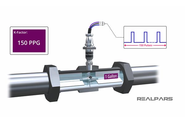
K = K-factor of the turbine meter (pulses per unit volume)
The K-factor represents the number of pulses produced per unit volume and varies with meter size and type. Each turbine meter is factory-calibrated for its specific application to ensure accuracy. This calibration guarantees precise measurement for the fluid type it’s designed for, whether measuring liquids or gases.

