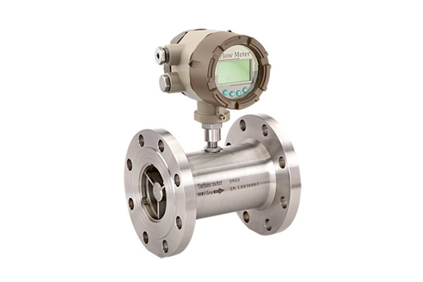

Turbine Flow Meter Manufacturer
As a leading Turbine Flow Meter Manufacturer and Supplier in Ahmedabad, Aranka Instruments LLP provides high-precision flow measurement solutions for diverse industrial applications. Our turbine flow meters are engineered to accurately measure clean, low-viscosity fluids such as water, fuel, and light oils with minimal pressure loss and exceptional repeatability. Built with robust stainless-steel construction and advanced magnetic pickup sensors, they ensure reliable performance and long service life. The precision-machined turbine rotor delivers stable readings even in demanding environments. Designed for easy integration, our models are available with both digital and analog outputs. Ideal for process control, automation, and monitoring systems.
Operating Principle
When fluid enters the turbine flow meter, it first passes through an inlet flow straightener that minimizes turbulence and ensures a uniform flow profile. The conditioned fluid then strikes the multi-blade turbine rotor, causing it to spin at a speed directly proportional to the flow velocity. As each blade moves through the magnetic field generated by the pickup sensor, an AC voltage pulse is produced. These pulses are transmitted to the flow transmitter or display unit, where the signal frequency corresponds precisely to the volumetric flow rate of the liquid.
- Simple and firm structure, easy for installation and dismantling.
- High resistance to electromagnetic interference and vibration.
- Small loss of pressure, fine repeatability and high precision.
- Wide range of measuring with very low lower flow velocity limit.
- The turbine flow meter is of hard alloy bearing thrust type, which may guarantee the precision and improve the wear resistance performance as well.
| Power | 24VDC | |
| Line Size | 20 mm to 200 mm | |
| Media | Any Clear Liquide | |
| Accuracy | +/- 1% / +/- 0.5% / +/- 0.2% of rate | |
| Body MOC | S.S.304, S.S.316 | |
| Rotor MOC | 2Cr13, CD4MCu | |
| Display | LCD | |
| Analogue Output | 4-20 mA | |
| Communication | RS485 [Optional] | |
| Electronics | Direct Mount | |
| Process Connections | DIN, ANSI Flanges, Tri-Clamp | |
| Bearing Material | Tungsten Carbide | |
| Max. Pressure | 0 – 15 Bar | |
| IP Protection | IP65 | |
| Temperature Range | Basic | -20°C to 80°C |
| Standard | -20°C to 120°C | |
| High | -20°C to 150°C | |
As per Application
- these are used in oil and gas,
- water and wastewater [Treated Water],
- chemical,
- power, food, and beverage,
- aerospace, pharmaceutical,
- metals and mining, and pulp and paper.
Frequently Asked Questions (FAQs)
What is a Turbine Flow Meter?
A turbine flow meter is an instrument that measures the volumetric flow rate of a fluid by using the mechanical rotation of a turbine placed in the flow path.
How does a Turbine Flow Meter work?
The fluid moves through the meter, rotating the turbine blades. The speed of rotation is proportional to the velocity of the fluid, which is converted into electrical pulses by the pickup sensor.
What type of fluids can it measure?
It is suitable for clean, low-viscosity liquids like water, fuel, oil, solvents, and light chemicals.
What are the advantages of Turbine Flow Meters?
They provide high accuracy, low cost, and simple installation, making them ideal for both industrial and commercial use.
How is the signal transmitted to the display?
The magnetic pickup sensor generates AC pulses that are processed by a transmitter or PLC to display the flow rate digitally.
What is the accuracy of a Turbine Flow Meter?
Typically, turbine flow meters offer accuracy levels of ±0.5% to ±1.0% of the reading, depending on model specifications and flow conditions.

