
Paddle Wheel Flow Meter Manufacturer
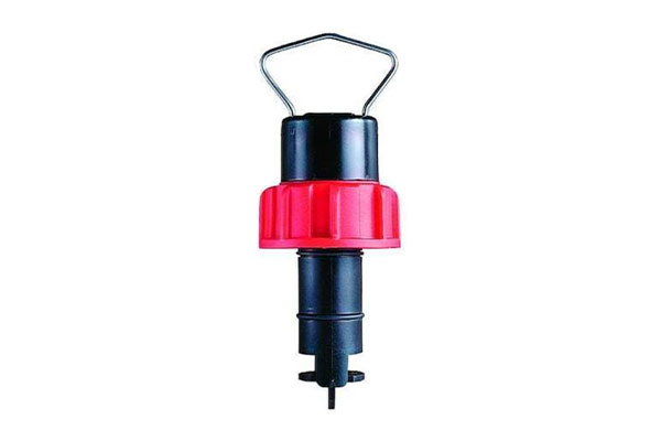
As a distinguished Paddle Wheel Flow Meter Manufacturer and Supplier, Aranka Instruments LLP delivers reliable, high-performance flow measurement solutions for fluid systems. Our paddle wheel meters use a rotating magnetic blade assembly to generate a frequency output proportional to flow velocity — the faster the fluid moves, the higher the pulse rate. These meters support both inline and insertion mounting, and are constructed in materials like PVDF, polypropylene, and stainless steel to suit various environments.
Recognized as a trusted Paddle Wheel Flow Meter Manufacturer in Ahmedabad, Gujarat, India and Paddle Wheel Flow Meter Supplier in Ahmedabad, we offer durable, easy-to-calibrate models that operate with minimal power and provide simple pulse outputs. Typical flow ranges vary by pipe size (e.g. 0.8–8 m³/h for 25 NB to 126–1260 m³/h for 300 NB), with accuracy of about 1 % of full scale. Built for low maintenance and effective in chemical, irrigation, and control systems, these meters are ideal for automated process environments.
- Low Power Operation
- Battery Operated Also Possible.
- Light Weight
- Easy To Calibration.
- Minimum run of straight pipe before and after the sensor.
- Simple Pulse Output.
| Flow Rate Range | 0.5 m/S to 5 m/S | |
| Accuracy | 1% of FSD | |
| Output | Pulse Square Wave of 5-12vdc, Amplitude 15-17.5 Hz/meter/Second | |
| Cable Length | 5 meter | |
| Protection | IP65 | |
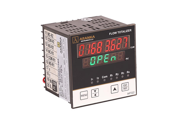
| Transmitter | AIFT22 Flow Indicator Controller | |
| Transmitter Power Supply | 90-260VAC | |
| Flow Range | 25 NB 0.8 ~ 8 M3/h | 150 NB 31 ~ 310 M3/h |
| 40 NB 1.9 ~ 19 M3/h | 200 NB 56 ~ 560 M3/h | |
| 50 NB 3.5 ~ 35 M3/h | 250 NB 87 ~ 870 M3/h | |
| 80 NB 7.5 ~ 75 M3/h | 300 NB 126 ~ 1260 M3/h | |
| 100 NB 14 ~ 140 M3/h | ||
| Operating Temperature | 0-60’C | |
| Operating Pressure | 0-10 Bar | |
Typical applications for paddle wheel flow meters include the accurate measurement of preset fluid volumes in dispensing systems, control of chemical metering pump output, flow verification, irrigation systems, and alerting users to flow rate increases or decreases outside a programmed range.
Frequently Asked Questions (FAQs)
What is a Paddle Wheel Flow Meter?
A Paddle Wheel Flow Meter is a mechanical device that measures the flow velocity of liquids by sensing the rotation speed of a paddle wheel placed in the flow path.
How does a Paddle Wheel Flow Meter work?
As liquid flows through the pipe, it spins the paddle wheel. Each rotation generates a pulse signal proportional to the flow rate, which is then converted into a digital or analog output.
What types of fluids can be measured?
It is suitable for clean and low-viscosity liquids such as water, chemicals, coolants, and light oils.
What are the advantages of using a Paddle Wheel Flow Meter?
-
Simple design and cost-effective measurement
-
Quick response to flow changes
-
Easy installation in existing pipelines
-
Low pressure drop and minimal maintenance
What is the accuracy level?
Typical accuracy is ±1% of full scale, depending on flow conditions and installation quality.
What materials are available?
Paddle wheel meters are available in PVDF, polypropylene, stainless steel, and PVC — chosen based on the application and fluid type.
Where are Paddle Wheel Flow Meters commonly used?
They are widely used in water treatment plants, chemical dosing systems, irrigation setups, cooling systems, and industrial process lines.
Do Paddle Wheel Flow Meters require maintenance?
They are low-maintenance instruments; however, periodic cleaning of the paddle and bearings ensures smooth operation and accuracy.

