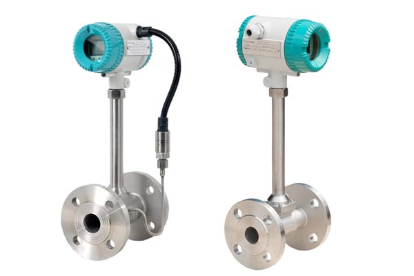
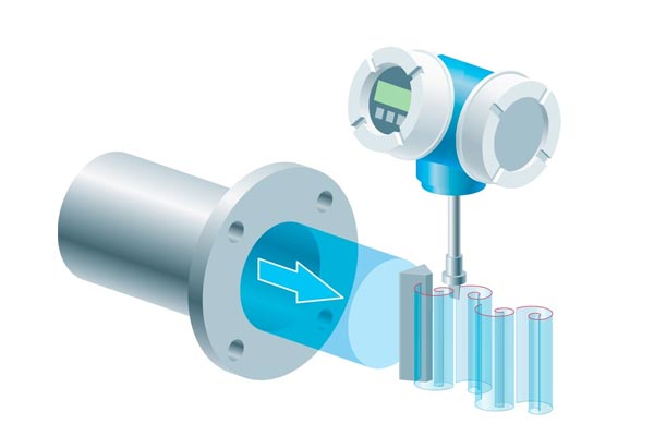
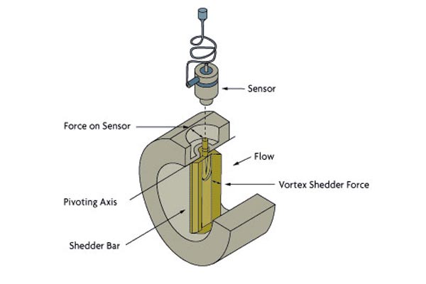
Vortex Flow Meters work on the Kármán Vortex Street principle, where a bluff body placed in the pipeline causes the fluid to form alternating vortices downstream. These vortices create pressure fluctuations that are detected by sensors.
The frequency of these vortices is proportional to the fluid’s velocity. Using this frequency, along with the known pipe diameter, the system calculates both mass and volumetric flow rates.
Key Components:
-
Bluff Body: Generates vortices in the fluid.
-
Sensors: Detect pressure and velocity changes.
-
Transmitter: Converts signals into accurate flow readings.
This design provides a robust, low-maintenance solution suitable for measuring liquids, gases, and steam with high precision.


Formulas & Measurement Principle
The frequency of vortex shedding is calculated using:
f=St×Vdf = \frac{St × V}{d}
Where:
-
ff = Vortex shedding frequency
-
StSt = Strouhal number (dimensionless)
-
VV = Flow velocity
-
dd = Width of bluff body
Once ff is known, volumetric flow rate (qq) is calculated as:
q=f×dkq = \frac{f × d}{k}
Strouhal number remains constant for Reynold’s numbers between 2×1042 × 10^4 to 7×1067 × 10^6, ensuring accuracy across varied flow conditions.
Types of Vortex Flow Meters
-
Insertion Flow Meter
This type has a built-in bluff body with sensors for vortex frequency, temperature, and pressure. The compact probe is inserted into the pipeline using flanged or NPT connections. It includes an LCD display and keypad for system settings and is ideal for pipes 2 inches or larger. Its retractable design allows installation without system shutdown. -
Inline Flow Meter
Unlike insertion meters, this replaces a pipeline section and measures all variables at a single point. It comes in two types:
a. Wafer-Style: Fits pipes up to 4 inches. Mounted between two flanges with precise alignment. Available in ANSI and Metric/DN flange standards.
b. Flanged-Style: Features flanged ends for direct connection to pipeline flanges, suited for larger pipes


