

Thermal Mass Flow Meter Manufacturer
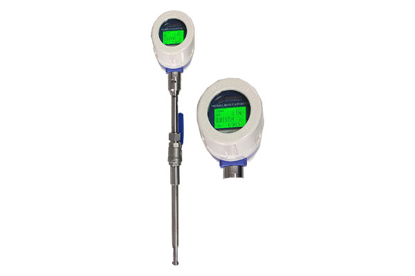
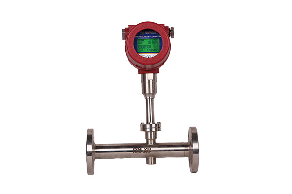
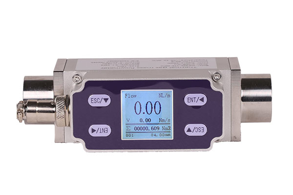
As a trusted Thermal Mass Flow Meter Manufacturer and Supplier in Ahmedabad, we specialize in advanced instruments that directly measure the mass flow rate of gases and air with high precision. Unlike volumetric flow meters affected by changes in temperature, pressure, viscosity, or density, our thermal mass flow meters deliver stable and accurate results under all ambient and process conditions. They are ideal for monitoring and controlling mass-based industrial processes, including chemical reactions that depend on the ratio of unreacted ingredients. Designed to measure even low gas flow rates, these meters ensure reliability and repeatability for applications in chemical, pharmaceutical, food, and environmental industries across Gujarat.
Operating Principle
Thermal mass flow meters are most often used for the regulation of low gas flows. They operate either by introducing a known amount of heat into the flowing stream and measuring an associated temperature change or by maintaining a probe at a constant temperature and measuring the energy required to do so. The components of a basic thermal mass flow meter include two temperature sensors and an electric heater between them. The heater can protrude into the fluid stream (Figure 5-8A) or can be external to
the pipe (Figure 5-8B).
In the direct-heat version, a fixed amount of heat (q) is added by an electric heater. As the process fluid flows through the pipe, resistance temperature detectors (RTDs) measure the temperature rise, while the amount of electric heat introduced is held constant. The mass flow (m) is calculated on the basis of the measured temperature difference (T2 – T1), the meter coefficient (K), the electric heat rate (q), and the specific heat of the fluid (Cp), as follows: m = Kq/(Cp(T2 – T1)
Heated-tube flow meters were developed to protect the heater and sensor elements from corrosion and any coating effects of the process. By mounting the sensors externally to the piping (Figure 5-8B), the sensing elements respond more slowly, and the relationship between mass flow and temperature difference becomes nonlinear. This nonlinearity results from the fact that the heat introduced is distributed over some portion of the pipe’s surface and transferred to the process fluid at different rates along the length of the pipe.
The pipe wall temperature is highest near the heater (detected as Tw in Figure 5-8B), while, some distance away, there is no difference between wall and fluid temperature. Therefore, the temperature of the unheated fluid (Tf) can be detected by measuring the wall temperature at this location further away from the heater. This heat transfer process is non-linear, and the corresponding equation differs from the one above as follows: m0.8 = Kq/(Cp(Tw – Tf))
This flow meter has two operating modes: one measures the mass flow by keeping the electric power input constant and detecting the temperature rise. The other mode holds the temperature difference constant and measures the amount of electricity needed to maintain it. This second mode of operation provides for a much higher meter rangeability.
- Lo Flow Measurement for Any Air or Gas.
- No Pipe Cutting.
- Easy Installation.
- Auto Pressure & Temperature Compensation.
- Very Low Pressure Lose.
- Direct Mass Flow Measurement.
| Power | 24VDC / 230VAC | |
| Line Size | 6 mm to 1200mm | |
| Sensitivity | 0.01 m/S | |
| Max. Velocity | 100 m/S | |
| Analogue Output | 4 – 20 mA | |
| Communication | RS485 Modbus RTU | |
| Accuracy | < 3% of Measuring Value | |
| Sensor MOC | S.S. 316 , S.S. 304 | |
| Process Connections | Thread/ Flange/ Try Clamp | |
| Electronics | Direct Mount | |
| Electronic Enclosure | Aluminum | |
| Display | LCD | |
| Operation Temperature | -20 ‘C ~ 150’C | |
| Calibration | Low Flow Cut-off, Zero Calibration, Flow Calibration, | |
As per application
- Gas Measurement
- HVAC, Wastewater, Manufacturing
- Compressed Air Measurement
- Seamless Integration
- In-Situ Calibration Validation
Frequently Asked Questions (FAQs)
What is a Thermal Mass Flow Meter?
It directly measures the mass flow rate of gases and air using heat transfer principles, unaffected by pressure or temperature changes.
How does it work?
It uses two RTDs — one heated, one unheated. The heat loss from the heated sensor is proportional to gas mass flow.
What gases can it measure?
Air, nitrogen, oxygen, CO₂, natural gas, hydrogen, and other clean industrial gases.
Where is it used?
In chemical plants, HVAC systems, gas distribution, and environmental monitoring.
What are the installation types?
Insertion, threaded, flanged, or tri-clamp connections are available.
What is its accuracy?
Typically within ±3% of the measured value, ensuring stable and precise readings.

