
What Should You Check Before Vortex Flow Meter Installation
Imagine a common scenario on the plant floor: a new meter is powered up and working, but its reading changes unexpectedly. The display jumps around, and the control room loses trust in the data. Often, the sensor itself is perfectly fine, but crucial pipe conditions, nearby valves, or configuration details were overlooked during setup. A successful Vortex Flow Meter Installation requires more than just bolting flanges together; it requires matching the instrument to the physical reality of your process line.
Whether you are managing a high-temperature steam line, a natural gas feed, or a liquid chemical process, ignoring basic mechanical and electrical rules will compromise your data. This guide covers the essential checks you must perform before installation, during mechanical mounting, and after startup. By reviewing the pipeline environment, confirming the straight run, and validating the electrical signal, you can avoid costly errors and ensure your new instrument provides accurate, reliable flow measurement from day one.
Quick Installation Answer
To get trustworthy data from your instrument, you must verify several key factors. First, confirm you have a suitable flow range and stable pipe conditions. Next, isolate the pipeline from heavy vibration and ensure the meter is physically mounted in the correct direction. Once installed, accurate configuration matches the meter’s electronics to the fluid properties. Finally, proper vortex flow meter commissioning verifies that the physical reading on the display perfectly matches the signal received by the plant’s control room.
Inspecting the Pipe Location Before Installation
Before cutting any pipe, look closely at what surrounds your chosen installation point. Bends, control valves, centrifugal pumps, and pipe reducers all create heavy turbulence. If the fluid enters the meter in a chaotic, swirling state, the sensor cannot measure the distinct alternating vortices it needs for an accurate flow calculation.
To fix this, you must provide enough undisturbed space upstream and downstream of the meter. Because vortex flow meter straight pipe requirements change dramatically depending on the exact disturbance—such as a single elbow, a double elbow out of plane, or a control valve—there is no single universal distance. You must follow the exact straight run lengths listed in your selected model’s manual and application drawing.
Checking the Process Conditions
The physical environment inside the pipe dictates how the meter will perform. First, verify the minimum and maximum flow rates. A vortex meter needs a minimum fluid velocity to generate detectable swirls. If the flow is too slow, the meter will read zero.
Next, confirm the operating temperature, pressure, and fluid type. A steam flow meter installation requires a sensor rated for high heat (such as a T2 or T3 level up to 350°C), while gas or liquid applications face different limits. Finally, if you are measuring liquids, ensure the pipe remains completely full of liquid at all times. Measuring a partially full pipe will immediately cause vortex flow meter inaccurate readings.
Mechanical Installation Checks
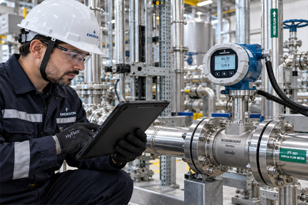
When bolting the meter into the line, always check the flow direction arrow stamped on the meter body. Installing the meter backward is a common mistake that guarantees failure. Ensure the pipe aligns perfectly with the meter flanges, and use gaskets that do not protrude into the pipe bore. Overhanging gaskets create artificial turbulence that ruins accuracy.
Heavy pipework must be supported independently; the meter body should never bear the weight of the pipeline. Additionally, isolate the meter from severe vortex flow meter vibration caused by nearby heavy machinery. Severe shaking can mimic the frequency of fluid vortices, causing false flow readings. Finally, mount the display where technicians have safe service access and protection from harsh weather, strictly following the orientation rules in the specific manual.
Electrical and Signal Configuration
A perfectly mounted meter will still fail if the electrical setup is flawed. The power supply—typically 24VDC for industrial 2-wire setups—must be stable and wired correctly. Route your signal cables far away from high-voltage power lines and variable frequency drives (VFDs). This prevents electromagnetic interference from corrupting your measurement data.
Verify that the output selection matches your plant’s control system. For example, Aranka Instruments provides models with a standard 4-20 mA 2-Wire output, as well as digital Modbus RS485 or Ethernet communication. You must also configure the display units (such as kg/hr for mass flow or m³/hr for volumetric flow) so the local LCD screen matches the exact values expected by the control room.
Commissioning Checklist
A structured checklist prevents startup surprises. Follow these ordered steps when powering up the device:
- Confirm the model and tags: Ensure the installed meter matches the purchasing specification and the plant’s piping diagrams.
- Verify configured units: Check that the LCD displays the correct engineering units for your specific fluid.
- Check flow direction: Confirm the physical arrow on the body points in the direction of actual fluid travel.
- Review process values: If the meter includes a built-in RTD and pressure sensor, verify that the displayed temperature and pressure match local mechanical gauges.
- Observe the displayed reading: Ensure the flow rate responds smoothly as the main line valves are slowly opened.
- Validate the control signal: Confirm that the 4-20 mA or Modbus signal exactly matches the value shown on the plant PLC or DCS screen.
- Test diagnostics and alarms: Check if the meter’s self-diagnostic function is reporting any active faults or wiring errors.
Common Installation Problems and Solutions
Use this troubleshooting table to identify potential causes when a new meter behaves unexpectedly. These are possible vortex flow meter troubleshooting starting points, not absolute diagnoses.
| Observed Issue | Possible Installation or Setup Cause | What to Check |
| Unstable or jumping flow readings | Upstream turbulence or a protruding flange gasket. | Check the straight pipe length against the manual and inspect the gasket alignment. |
| No reading during active flow | Flow velocity is below the meter’s minimum measurable threshold. | Check the actual minimum flow rate against the meter’s specified Reynolds number limits. |
| The meter shows a reading at no flow | Mechanical shaking is mimicking fluid vortices. | Inspect for pipe vibration from nearby pumps and add rigid pipe supports. |
| Readings do not match expected consumption | The fluid density setup is incorrect for the actual operating temperature. | Verify the temperature and pressure configuration, especially for superheated steam applications. |
Illustrative Example: Troubleshooting Near an Elbow
Illustrative Example: A maintenance team installs a new vortex meter just downstream of a 90-degree elbow on a factory cooling water line. Upon startup, the flow reading fluctuates wildly, even though the pump is running at a constant, steady speed.
The team reviews the manufacturer’s vortex flow meter installation guidelines and realizes the elbow is distorting the flow profile right before it reaches the sensor. Instead of altering the pump or replacing the meter, they relocate the meter further down the line to satisfy the required straight pipe distance specified in the manual. Once moved, the fluid flow stabilizes before hitting the sensor, and the digital display provides a steady, accurate reading.
Questions to Ask Before Accepting the Installation
Before signing off on a new installation provided by a contractor or an EPC team, ask these key handover questions to ensure long-term success:
- Are the final installation drawings updated to show the exact meter location?
- Is there a documented record of the final configuration parameters, including pipe size and density?
- Has the specific model’s operating manual been physically handed over to the maintenance team?
- Are the factory calibration documents and certificates safely filed?
- If the readings begin to drift over the next month, who is responsible for providing technical support?
Conclusion
Accurate flow measurement is never an accident; it is the result of careful planning and strict adherence to mechanical and electrical rules. By respecting straight pipe requirements, managing vibration, configuring outputs correctly, and following a disciplined commissioning process, you can trust the data your instrument provides.
When you are ready to upgrade your facility’s instrumentation, discuss your application with an experienced vortex flow meter manufacturer. Review Aranka Instruments’ Vortex Flow Meters to find reliable solutions equipped with built-in temperature and pressure compensation, advanced anti-vibration processing, and the correct outputs for your plant.
FAQs
The required straight pipe distance depends entirely on the type of upstream disturbance, such as a single elbow, a valve, or a reducer. Because there is no universal distance, you must always consult your specific model’s installation manual for the exact upstream and downstream pipe requirements.
Installing a meter immediately next to a valve or elbow causes severe turbulence, which prevents the sensor from reading distinct alternating vortices. You must install the meter at the required straight pipe distance away from these pipe fittings to ensure a smooth, uniform flow profile.
Yes, heavy mechanical vibration from nearby pumps or compressors can mimic the frequency of fluid vortices, causing the meter to register false flow rates. To prevent this, ensure the pipeline is rigidly supported and isolate the meter from severe shaking before commissioning.
Before installation, verify the maximum steam temperature and operating pressure to ensure they do not exceed the sensor’s design limits. You must also confirm whether you are measuring saturated or superheated steam, so the meter can accurately compensate for density changes.
If a meter displays a flow reading while the fluid is completely stopped, the cause is usually mechanical vibration. The sensor is picking up the shaking of the pipeline and misinterpreting it as flow vortices. Adding proper rigid pipe supports usually solves this issue.
A new meter should arrive with a comprehensive operating manual, a factory calibration certificate, and an application or wiring drawing. These documents are essential for correct electrical setup, parameter configuration, and future maintenance troubleshooting.
Yes, reviewing the application before purchase is crucial. Buyers can consult with Aranka Instruments’ technical team to confirm pipe sizing, straight run availability, and fluid compatibility, ensuring the selected model will provide accurate, trouble-free measurement for the facility.