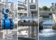


EM Flow Meter Installation & Common Errors
Accurate liquid flow measurement is critical for process control, chemical dosing, and utility management, but even the highest-quality instrument will fail if installed improperly. A proper electromagnetic flow meter installation ensures reliable data, while poor mechanical or electrical practices lead to immediate operational headaches. Incorrect installation can cause a cascade of frustrating issues, including unstable readings, zero flow indications, negative flow values, false empty-pipe alarms, and persistent communication problems.
Plant operators and engineers often spend hours troubleshooting perceived instrument failures when the root cause is simply a bad mounting location, inadequate grounding, or a partially filled pipe. Aranka Instruments LLP frequently helps plant operators resolve these exact issues. This comprehensive guide covers the essential steps for successful magnetic flow meter installation, identifies common errors to avoid, and provides practical troubleshooting strategies to ensure your measurement system performs accurately from day one.
What Is an Electromagnetic Flow Meter?
An electromagnetic flow meter, commonly called a mag meter, is a volumetric flow measurement device designed specifically for electrically conductive liquids. It operates based on Faraday’s law of electromagnetic induction. As conductive fluid passes through a magnetic field generated by the meter’s internal coils, it induces a small electrical voltage.
This voltage is directly proportional to the fluid’s velocity. Metal electrodes mounted inside the flow tube detect this voltage, and an electronic transmitter calculates the corresponding volumetric flow rate. Because there are no moving parts to obstruct the flow path, pressure drop is virtually non-existent. For a deeper understanding of the physics behind this process, you can refer to our detailed electromagnetic flow meter working principle guide.
Where Electromagnetic Flow Meters Are Used
These instruments are highly versatile and rugged, making them a staple in heavy industry and municipal utilities. However, they have strict operational parameters. They are exclusively designed for conductive fluids and cannot measure oil, fuel, gas, or non-conductive liquids like pure deionized water. Common applications include:
- Water supply and municipal distribution networks
- Wastewater and raw sewage handling
- ETP (Effluent Treatment Plant) and STP (Sewage Treatment Plant) facilities
- Chemical processing and precise additive dosing systems
- Cooling water loops in manufacturing and HVAC facilities
- Slurry-compatible applications in mining, cement, and pulp processing
- Food processing and beverage production facilities
- Industrial utilities and process plants requiring strict fluid control
Before selection, plant engineers must confirm that the liquid conductivity meets the minimum threshold (typically around 5 µS/cm) and that the selected liner and electrode materials are chemically compatible with the process fluid.
Pre-Installation Checks
Before moving the instrument to the pipeline, verifying system parameters prevents costly rework.
Gather all technical data to ensure the flow meter matches the process conditions perfectly.
| Pre-Installation Checklist | Parameter to Verify |
|---|---|
| Liquid Conductivity | Must be electrically conductive. No oils, fuels, or gases. |
| Pipe Diameter | Must match the meter size or require appropriately sized reducers. |
| Flow Range | Normal operating flow should fall within the meter’s optimal velocity range. |
| Temperature | Maximum process temperature must not exceed the internal liner rating. |
| Pressure | Line pressure must remain below the flange and body pressure classes. |
| Liner Material | Must resist chemical attack and mechanical abrasion from the process fluid. |
| Electrode Material | Must be chemically compatible with the liquid (e.g., Hastelloy for acids). |
| Pipe Material | Determines grounding ring requirements (conductive metal vs. non-conductive plastic). |
| Flange Rating | Ensure matching bolt hole patterns and pressure ratings (e.g., ANSI, DIN). |
| Power Supply | Verify available voltage matches the transmitter (e.g., 24V DC, 230V AC). |
| Output Signal | Confirm 4-20mA, pulse, or alarm output requirements. |
| Communication Protocol | Check for RS485 Modbus, HART, or Profibus integration needs. |
| Transmitter Type | Choose integral or remote based on vibration and environmental conditions. |
| Maintenance Accessibility | Ensure enough clearance around the meter for future servicing. |
Electromagnetic Flow Meter Installation Procedure
Inspect the meter and accessories: Check for transit damage before lifting. Do not lift the meter by the transmitter casing.
Confirm the model and pipe size: Ensure the instrument matches site drawings and pipeline dimensions.
Check the flow-direction arrow: Locate the arrow stamped on the sensor body and align it with the fluid flow.
Select a proper location: Choose a pipeline section that guarantees a completely filled pipe under all operating conditions.
Avoid air pockets: Place the meter at lower elevations in the piping network where air bubbles cannot gather.
Avoid pump suction: Never install the meter directly on pump suction to prevent vacuum damage to the liner.
Position the electrodes correctly: In horizontal runs, ensure the measurement axis is strictly horizontal.
Align the pipe flanges: Pipes must align properly without using the meter’s flange bolts to force the gaps closed.
Install suitable gaskets: Use compatible gaskets that do not protrude into the flow stream.
Tighten bolts evenly: Apply torque in a crisscross pattern to prevent crushing the liner or cracking the flanges.
Check grounding and earthing: Install grounding rings if required and securely tie the meter to a clean earth ground.
Route cables correctly: Keep low-voltage signal cables separated from high-voltage power trays to prevent noise.
Configure parameters: Enter the correct flow units and pipe dimensions into the transmitter menu.
Verify zero conditions: Fill the pipe completely, stop the flow entirely, and perform a zero calibration if needed.
Horizontal Pipe Installation
When executing a magnetic flow meter installation horizontally, electrode orientation is critical. The meter must be rotated so the measuring electrodes sit directly on the horizontal axis (the 3 o’clock and 9 o’clock positions).
If the meter is installed with electrodes on the vertical axis (12 o’clock and 6 o’clock), you risk immediate failures. Air bubbles naturally travel at the top of the pipe and can break the electrical circuit at the top electrode. Conversely, sediment and sludge settle at the bottom and can insulate the bottom electrode. Proper horizontal orientation prevents both an empty pipe error and signal loss.
Vertical Pipe Installation
Vertical pipelines often provide excellent locations for electromagnetic flow meters, provided the flow direction is upward. Pumping fluid upward against gravity ensures the pipeline remains completely full of liquid at all times, which is a mandatory condition for accurate measurement.
Downward flow should always be avoided. Gravity can pull liquid down the vertical drop faster than the pipeline fills from upstream, creating a partially filled pipe. This leads to erratic readings, severe signal bounce, and false empty-pipe alarms.
Straight-Pipe Requirements
For stable velocity profiles, the fluid must travel through a straight, unobstructed pipe section before and after the meter. Various pipeline components cause turbulence that severely disturbs the flow profile, including:
- Pumps (centrifugal and positive displacement)
- Elbows and sharp bends
- Tees, cross joints, and y-strainers
- Pipe reducers and expanders
- Control valves and regulators
- Partially open isolation valves
- Multiple bends in different planes
We cannot provide one universal straight-pipe requirement because every piping scenario is unique. You must strictly follow the selected model’s official product-specific installation manual to determine the exact upstream and downstream straight-pipe distances required for your layout.
Electromagnetic Flow Meter Grounding and Earthing
Electromagnetic flow meter earthing is arguably the most critical electrical requirement during installation. Without proper grounding, stray electrical noise from variable frequency drives, pumps, and facility power grids will distort the weak millivolt signal generated by the liquid.
Why is grounding important for an electromagnetic flow meter?
Grounding provides a stable reference potential for the meter’s measuring circuit. It ensures the conductive liquid and the transmitter share the exact same electrical zero point. Proper grounding eliminates electrical noise and stray currents, preventing erratic flow readings, severe signal drift, and false empty-pipe alarms.
The grounding method depends on your piping material:
- Conductive Pipes: Metal pipes naturally ground the fluid. The meter’s grounding wire connects directly to the metal flanges.
- Non-Conductive Pipes: Plastic, PVC, fiberglass, or internally lined pipes cannot ground the fluid. Grounding rings (or specialized grounding electrodes) must be installed between the flanges to touch the liquid and provide a path to earth.
Always use high-quality shielded cables and ensure proper cable separation to block induced electrical noise.
Most Common Electromagnetic Flow Meter Installation Errors
Even experienced technicians occasionally face setbacks. Watch out for these frequent mistakes:
- Partially filled pipe: The absolute leading cause of erratic data and poor performance.
- Wrong flow direction: Installing the instrument backward relative to the process flow.
- Poor grounding: Missing earth connections or forgetting grounding rings on non-conductive pipes.
- Air bubbles: Trapped air altering the fluid’s volume and breaking electrode contact.
- Empty pipe: Draining lines triggering an empty pipe error on the transmitter.
- Incorrect electrode orientation: Electrodes placed on the vertical axis in horizontal pipe runs.
- Incorrect liner selection: Liner melting or tearing due to incompatible chemicals or temperatures.
- Incorrect electrode material: Chemical corrosion quickly destroying the measuring pins.
- Gasket obstruction: Gaskets squeezing into the pipe ID and creating turbulence.
- Poor flange alignment: Stressing the meter body and damaging the internal liner.
- Excessive vibration: Shaking the sensitive electronics inside an integral transmitter.
- Pump suction installation: Placing the meter before a pump, leading to vacuum damage.
- Incorrect cable routing: Creating severe electromagnetic interference.
- Wrong meter configuration: Entering incorrect pipe sizes or output units into the transmitter.
- Electrical interference: Unresolved ground loops disrupting the final flow signal.
Common Symptoms and Possible Causes
Use this practical troubleshooting table to diagnose typical issues quickly.
| Symptom | Possible Causes | Recommended Checks |
|---|---|---|
| Zero Reading (While Flowing) | Closed downstream valves, reversed flow direction, severed signal cable. | Verify actual flow exists, check flow arrow direction, inspect wiring continuity. |
| Unstable Reading | Poor grounding, air bubbles, partially full pipe, electrical noise. | Test earth connection, check for air traps, separate power and signal cables. |
| Negative Reading | Reversed flow direction, reversed signal wires at the terminal block. | Check physical installation direction and flip terminal block wiring if necessary. |
| Reading Too High | Gasket obstruction causing velocity spikes, wrong pipe size programmed. | Inspect flange gaskets for protrusion, verify transmitter menu configuration. |
| Reading Too Low | Insulating coating on electrodes, incorrect flow units selected. | Clean electrodes, review and correct menu parameter settings. |
| Intermittent Signal | Loose terminal connections, fluctuating or dipping power supply. | Tighten all wiring terminals, measure input voltage stability. |
| Empty-Pipe Alarm | Pipe is actually empty, electrodes not touching liquid, heavy electrode scaling. | Ensure pipe is totally full, rotate meter to horizontal axis, clean sensor. |
| No Analog Output | Blown internal fuse, incorrect loop wiring, inactive output mode. | Check 4-20mA loop continuity, verify active/passive mode switch. |
| Communication Failure | Wrong baud rate, incorrect slave address, reversed RS485 wires. | Confirm protocol settings match the PLC or SCADA system perfectly. |
Electromagnetic Flow Meter Commissioning Checklist
Before handing the system over to plant operations, walk through this flow meter commissioning checklist:
- [ ] Meter model and tag number verified against P&ID.
- [ ] Pipe size matches the meter bore properly.
- [ ] Flow direction arrow aligned with actual process flow.
- [ ] Pipe is confirmed completely full of fluid under normal operating pressure.
- [ ] Grounding completed (including grounding rings if mounted on non-conductive pipes).
- [ ] Cable routing checked for separation from high-voltage trays.
- [ ] Power supply verified and matches terminal requirements.
- [ ] Engineering units configured correctly in the transmitter display.
- [ ] Analog (4-20mA) or pulse output tested with the central control room.
- [ ] PLC or SCADA communication (Modbus/HART) tested and verified.
- [ ] Leakage checked at all flange connections under full line pressure.
- [ ] Zero reading checked under full pipe, absolutely no-flow conditions.
- [ ] Final dynamic reading recorded and approved by the process engineer.
Maintenance and Calibration Recommendations
An electromagnetic flow meter requires minimal physical maintenance since it lacks moving parts. However, scheduled checks keep accuracy high over the instrument’s lifespan.
- Electrode inspection: Periodically clean electrodes if the process fluid deposits scale, fats, or grease.
- Liner inspection: Check for blistering or abrasion, especially in abrasive slurry applications.
- Grounding inspection: Verify earth continuity, as corrosion can degrade ground connections over time.
- Cable checks: Ensure moisture has not entered the terminal box and compromised the wiring.
- Empty-pipe verification: Simulate an empty pipe to confirm the transmitter generates the correct alarm.
- Zero verification: Stop flow periodically while keeping the pipe full to verify the meter reads zero.
- Comparison: Conduct a comparison with a portable reference measurement tool if process conditions allow.
- Calibration records: Maintain detailed electromagnetic flow meter calibration records for audits.
Note that we do not provide one universal calibration interval. Calibration frequency depends entirely on regulatory requirements, process severity, and the specific quality control standards at your facility.
Electromagnetic Flow Meter Support from Aranka Instruments
If you are facing complex piping layouts or aggressive process fluids, Aranka Instruments LLP is here to help. As a leading industrial flow meter supplier, we specialize in high-quality measurement solutions tailored to your plant’s specific needs.
Based in Ahmedabad, Gujarat, our team supports heavy industry and municipal projects across India with technical expertise, fast response times, and dependable instrumentation. From heavy-duty wastewater monitoring to precise chemical dosing, we guide you through proper selection, sizing, and commissioning. For very large pipelines where traditional flanged meters are economically or practically unfeasible, we also provide expert guidance on the insertion electromagnetic flow meter.
Conclusion
Proper installation is the foundation of reliable industrial flow measurement. By maintaining a completely full pipe, strictly observing grounding protocols, ensuring chemical compatibility, and avoiding flow disturbances, you can eliminate the most common operational errors. Whether you are dealing with fluctuating readings or planning a new plant expansion, taking the time to follow this guide will save endless troubleshooting hours down the line.
Are you ready to optimize your process measurement? Contact our engineering team to discuss your application. Please provide us with the following details for a precise recommendation:
- Liquid name
- Conductivity
- Pipe size
- Flow range
- Temperature
- Pressure
- Pipe material
- Liner preference
- Electrode preference
- Output requirement
- Integral or remote transmitter requirement
Frequently Asked Questions
An electromagnetic flow meter should be installed in a pipeline location that guarantees a completely full pipe at all times. It requires proper alignment of the electrodes on the horizontal axis, secure flange bolting, and strict adherence to grounding protocols. Always follow the manufacturer’s specific straight-pipe guidelines to ensure an undisturbed velocity profile.
Yes, an electromagnetic flow meter absolutely requires a completely full pipe to function correctly. The electrodes located inside the flow tube must maintain constant contact with the liquid. If the pipe is only partially full, the circuit breaks, leading to highly erratic readings, unstable outputs, or persistent empty-pipe alarms on the transmitter.
Yes, it can be installed vertically, but upward flow is highly recommended. Pumping fluid upward against gravity naturally ensures the pipeline remains completely full of liquid. Installing the meter in a downward-flowing vertical pipe often causes partial filling as gravity pulls the liquid away faster than the pipe can fill, disrupting measurements.
Grounding is vital because it establishes a stable electrical zero potential between the conductive fluid and the transmitter. Without proper grounding, stray electrical noise from variable frequency drives, pumps, or nearby machinery will distort the tiny millivolt signal generated by the flow. Good earthing guarantees accurate readings and stable output signals.
No, a magnetic flow meter cannot measure oil, fuel, petroleum products, or natural gas. These meters rely on Faraday’s law of electromagnetic induction, which strictly requires the fluid to be electrically conductive. Oil and similar hydrocarbons act as insulators and lack the necessary conductivity to generate a readable voltage signal.
Unstable flow readings are most frequently caused by a partially filled pipe, trapped air bubbles, or poor electrical grounding. Flow disturbances from nearby pumps, half-open control valves, or elbows placed too close to the meter can also severely disrupt the velocity profile, causing the transmitter output to fluctuate erratically.
It should always be installed on the discharge side of a pump, never on the suction side. Installing a flow meter on the suction side exposes it to extreme turbulence and vacuum conditions. Vacuum forces can cause the internal liner to collapse, permanently destroying the meter’s flow tube and accuracy.
There is no single universal straight-pipe requirement, as it depends on upstream disturbances. However, typical industry guidelines suggest maintaining five to ten pipe diameters upstream and two to five pipe diameters downstream. You must consult your specific flow meter’s technical manual to determine the exact requirements for your chosen model.
An empty-pipe alarm triggers when the measuring electrodes lose contact with the conductive fluid. This happens if the pipeline physically drains, if heavy air pockets gather at the top of a horizontally installed meter, or if severe scaling completely coats the internal electrodes and isolates them from the liquid.
There is no universal calibration interval for these meters. Calibration frequency depends on your facility’s quality standards, regulatory requirements, and the harshness of the process fluid. Some critical industrial plants verify calibration annually, while clean-water utilities might operate safely for several years before requiring comprehensive verification or recalibration services.