
Paddle Wheel Flow Meter Working Principle Installation and Uses
Accurate liquid flow measurement plays a vital role in modern industrial systems, helping plants maintain process efficiency, control material costs, and ensure regulatory compliance. Among various monitoring tools, the paddle wheel flow meter stands out as a reliable and cost-effective choice for clean water, chemical processing, and general fluid management.
By balancing simplicity with dependable mechanical operation, this instrument provides clear data on both instantaneous flow and cumulative volume. Understanding how it operates, how to install it correctly, and where to apply it ensures smooth plant operations and long-term instrument reliability.
What Is a Paddle Wheel Flow Meter?
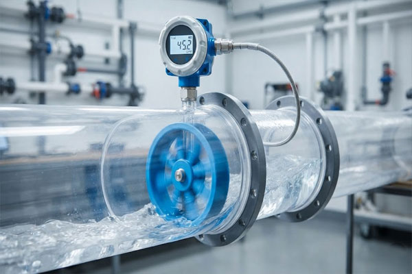
A paddle wheel flow meter is a velocity-based instrument designed to measure the rate of liquid flowing through a closed pipeline. It converts mechanical rotor movement into electrical pulses, allowing operators to measure both flow rate and cumulative volume.
Typical liquids include clean water, RO permeate, cooling tower water, mild acids and compatible chemical additives.
Main Components of a Paddle Wheel Flow Meter
Paddle Wheel Flow Meter Working Principle
Types of Paddle Wheel Flow Meters
Paddle Wheel Flow Meter Installation Guide
Proper installation ensures stable performance and reliable measurements.
Horizontal Installation
Paddle wheel flow meters can be installed on horizontal pipelines. Mounting the sensor on the top half of the pipe helps prevent sediment buildup from fouling the rotor.
Vertical Installation
For vertical pipelines, upward flow is normally preferred because it helps keep the pipe completely full. Downward flow can cause incomplete filling and erratic readings.
Common Installation Mistakes
- Incorrect insertion depth
- Installing against flow direction
- Partially filled pipe
- Air pockets around the sensor
- Installing immediately after turbulent valves or pumps
- Incorrect pipe-size configuration
- Excessive pipeline vibration
- Incompatible liquid chemistry
- Poor electrical connections
- Mineral or biological deposits on the paddle wheel
Industrial Uses
- Water treatment plants
- RO plants
- ETP and STP plants
- Chemical dosing systems
- Cooling-water systems
- Irrigation systems
- HVAC chilled-water loops
- Process-water monitoring
- Liquid dispensing and batching
- General industrial automation
Advantages of Paddle Wheel Flow Meters
- Simple mechanical design
- Cost-effective purchase and installation
- Low pressure drop
- Easy sensor removal for inspection
- Clear local displays and standard outputs
- Suitable for various pipe sizes
Limitations of Paddle Wheel Flow Meters
- Highly viscous liquids
- Dirty liquids with heavy debris or fibers
- Abrasive liquids
- High-solid slurries
- Liquids with solids that can wrap around the rotor
- Very low flow velocity
How to Select the Right Paddle Wheel Flow Meter
- Liquid name and chemical properties
- Pipe size and material
- Minimum and maximum flow rates
- Expected flow velocity
- Operating temperature and pressure
- Wetted-part material compatibility
- Insertion or inline installation
- Pulse or analog output
- Local display requirement
- Totalizer requirement
- Power supply availability
- Maintenance accessibility
Paddle Wheel Flow Meter Selection Checklist
| Parameter | Consideration |
|---|---|
| Fluid Type | Must be clean or lightly treated and free of heavy solids. |
| Pipe Size | Match insertion length or inline diameter precisely. |
| Flow Range | Ensure normal flow sits in the middle third of the operating range. |
| Temperature | Verify sensor body and O-ring limits. |
| Pressure | Confirm fitting and body ratings exceed line pressure. |
| Output | Select pulse, 4-20mA or digital display as needed. |
Paddle Wheel Flow Meter vs Electromagnetic Flow Meter
| Feature | Paddle Wheel Flow Meter | Electromagnetic Flow Meter |
|---|---|---|
| Working Principle | Mechanical rotor velocity measurement | Faraday’s law of electromagnetic induction |
| Liquid Conductivity | Not required | Required |
| Moving Parts | Yes | None |
| Pressure Loss | Very low | Negligible |
| Maintenance | Periodic rotor cleaning required | Minimal |
| Cost | Economical | Higher investment |
| Liquid Suitability | Clean water and compatible chemicals | Water, wastewater, slurries and acids |
| Applications | Water treatment, HVAC, RO systems | Effluent plants, chemical processing, mining |
Maintenance Tips
- Clean rotor and shaft periodically.
- Inspect sensor body and O-rings.
- Verify free rotor movement manually.
- Check sensor wiring and moisture ingress.
- Check leakage around the fitting.
- Compare output with a secondary reference meter during calibration checks.
Paddle Wheel Flow Meters from Aranka Instruments
Aranka Instruments LLP provides paddle wheel flow meters and related flow measurement instruments for industrial applications. Based in Ahmedabad, Gujarat, India, the company supports process water, irrigation and utility monitoring applications with practical engineering, clear local readouts and dependable signal transmission.
Conclusion
Paddle wheel flow meters offer a balanced combination of mechanical simplicity, reliable performance and cost-effectiveness for clean-liquid applications. Correct installation and proper fluid selection help ensure dependable flow data.
For a precise recommendation, provide the following application details:
- Liquid name
- Pipe size
- Flow range
- Temperature
- Pressure
- Output requirement
- Installation type
Technically reviewed by the Aranka Instruments engineering team.
Frequently Asked Questions
A paddle wheel flow meter is a velocity-measuring instrument that uses a small spinning rotor placed in a liquid stream. The sensor converts rotor movement into electrical pulses representing flow rate and total volume.
Fluid flowing through the pipe rotates the paddle wheel. Rotational speed follows fluid velocity, and the sensor converts each blade pass into an electrical signal that the transmitter turns into a readable flow value.
These meters are best suited for clean water, RO permeate, cooling water, light chemicals and other low-viscosity, non-abrasive liquids.
Yes. Upward vertical flow is normally preferred because it helps keep the pipe completely full and maintains steady contact between the liquid and rotor.
Yes. Partial filling can create air pockets and irregular rotor movement, causing inaccurate readings.
The correct depth places the rotor in the active flow stream and should follow the manufacturer’s specified immersion depth for the pipe diameter and fitting type.
Standard paddle wheel meters are generally unsuitable for raw wastewater because solids, debris and rags can foul or damage the rotor. They may be used on well-filtered treated effluent.
Common causes include air bubbles, incomplete pipe filling, incorrect pipe-size configuration, improper insertion depth and sediment buildup on the rotor blades.
Inspection frequency depends on fluid cleanliness. The source notes that six-month rotor and shaft checks are common for clean-water applications, with harsher services requiring more frequent inspection.
Evaluate liquid properties, pipe size, minimum and maximum flow rates, operating temperature, pressure limits, wetted materials and output requirements.